17. November 2010
Netzwerk erstellen mit Server und Client
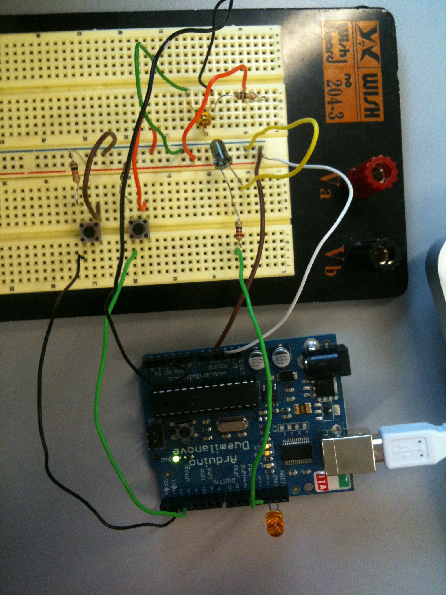
 Server:
- Vor dem Lichtsensor befindet sich ein 100K Widerstand
- Vor den Knöpfen befinden sich 10K Widerstände
Server:
- Vor dem Lichtsensor befindet sich ein 100K Widerstand
- Vor den Knöpfen befinden sich 10K Widerstände
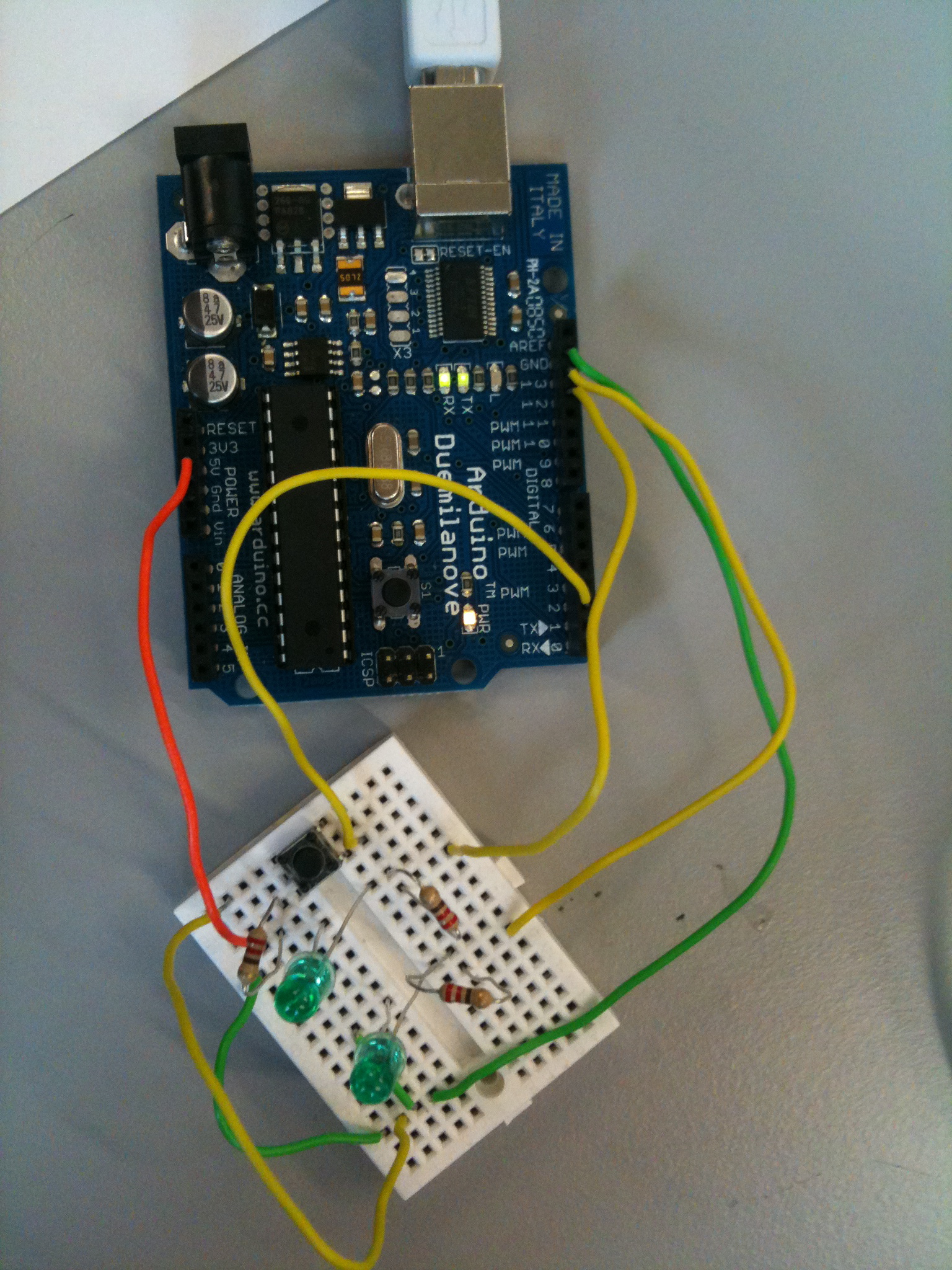
 Client:
 Server:
/* Processing Network Server controlling an Arduino

Arduino #1   is an IN and OUTPUT Device,
             connected to a Machine that runs a Processing Network Server
Arduino #2   is ALSO an IN and OUTPUT Device,
             connected to a Machine that runs a Processing Network Client

This is the SERVER. You have to find out your IP address and start it before the Client...
You can then send and receive data on both machines/ arduinos.
On both Arduinos we read DIN2, DIN3, and AIN0. This can be expanded of course.
We send the data in a byte array with a header of the number 255 -> [255, DIN2, DIN3, AIN0]
On the receiving end we map DIN2 to DOUT12, DIN3 to DOUT13 and AIN0 to DOUT9 (PWM).
*/

// Libraries -----------------------------
import processing.serial.*;
import cc.arduino.*;
import processing.net.*;

// Variables -----------------------------
Arduino arduino;
Server myServer;

color off = color(4, 79, 111);
color on = color(84, 145, 158);

// byte array to send
// [255, DIN2, DIN3, AIN0]
byte[] input = {byte(255), byte(0), byte(0), byte(0)};

// int array to receive data
int[] message = {0,0,0,0};
int dataInput = 0;

// Setup ---------------------------------
void setup() {
  size(470, 280);
  arduino = new Arduino(this, Arduino.list()[0], 57600);

  // Set pins 2 - 3 as Inputs
  for (int i = 2; i <= 3; i++)
    arduino.pinMode(i, Arduino.INPUT);

  // Set pins 13, 12, 9 as outputs
  for (int j = 12; j <= 13; j++)
    arduino.pinMode(j, Arduino.OUTPUT);

    arduino.pinMode(9, Arduino.OUTPUT);
    arduino.digitalWrite(13, Arduino.LOW);

  // start server
  myServer = new Server(this, 5204);

}

// Draw Loop ----------------------------------------------------
void draw() {
  background(off);
  stroke(on);

// read DIN2, DIN3 -----------------
  for (int x = 2; x <= 3; x++){
    if (arduino.digitalRead(x) == Arduino.HIGH){
      input[x-1] = 1;
      fill(on);
    }
    else {
      input[x-1] = 0;
      fill(off);
    }
   rect(420 - x * 30, 30, 20, 20);
  }

// check AIN0, scale to 0-255 and make it 254 if it is 255
// because 255 is used as header of our little protocol
  byte val = byte(arduino.analogRead(0) / 4);
  if (val == 255){
    val -= 1;
  }

  input[3] = val;

  // send data ----------------------------
  myServer.write(input);

  // read data ----------------------------
  Client thisClient = myServer.available();
  if (thisClient != null){
    dataInput = thisClient.read();
    if (dataInput == 255){
      message[0] = 255;
      message[1] = thisClient.read();
      message[2] = thisClient.read();
      message[3] = thisClient.read();
    }
  }
  println(message);

  // control arduino with the received data ---
  if (message[1] == 1){
    arduino.digitalWrite(12, Arduino.LOW);
  }
  if (message[1] == 0){
    arduino.digitalWrite(12, Arduino.HIGH);

  }

  // println(arduino.analogRead(2));
  if (arduino.analogRead(2) < 100){
    arduino.digitalWrite(13, Arduino.HIGH);
  }
  else {
    arduino.digitalWrite(13, Arduino.LOW);
  }

   arduino.analogWrite(9, message[3]);

  // draw analog inputs in window ---
  for (int i = 0; i <= 5; i++) {
    ellipse(280 + i * 30, 240, arduino.analogRead(i) / 16, arduino.analogRead(i) / 16);
  }
}
Client:
/* Processing network Client controlling an Arduino

Arduino #1   is an IN and OUTPUT device
             connected to a Machine that runs a Processing Network Server
Arduino #2   is ALSO an IN and OUTPUT device
             connected to a machine that runs a Processing Network Client

This is the Client. Get the Server's IP address and start the server first.
You can then send and receive data on both machinges/ arduinos.
On both Arduinos we read DIN 2, DIN3 and AIN0. This can of course be expanded...
We send the data in a byte array with a header of the number 255 -> [255, DIN2, DIN3, AIN0]
On the receiving end we map DIN2 to DOUT 12, DIN3 to DOUT 13 and AIN0 to DOUT9 (PWM).

*/

// libraries ---------------------
import processing.serial.*;
import cc.arduino.*;
import processing.net.*;

// variables ---------------------
Arduino arduino;
Client myClient;

color off = color(4, 79, 111);
color on = color(84, 145, 158);

byte[] input = {byte(255), byte(0), byte(0), byte(0)};
byte val;

int[] message = {0, 0, 0, 0};

int dataInput;

// setup ---------------------------------------------------
void setup() {
  size(200, 200);

  println(Arduino.list());
  arduino = new Arduino(this, Arduino.list()[0], 57600);

  for (int i = 12; i <= 13; i++)
    arduino.pinMode(i, Arduino.OUTPUT);

  arduino.pinMode(9, Arduino.OUTPUT);

  for (int i = 2; i <= 3; i++)
    arduino.pinMode(i, Arduino.INPUT);

  myClient = new Client(this, "172.31.8.192", 5204);


}

// the draw loop -------------------------------------------
void draw() {
  background(off);
  stroke(on);

  // read data from server ------------------
  if (myClient.available() > 0){
    dataInput = myClient.read();

  // check for 255 and read thereafter
  // [255, DIN2, DIN3, AIN0]
    if (dataInput == 255){
      message[0] = dataInput;
      message[1] = myClient.read();
      message[2] = myClient.read();
      message[3] = myClient.read();
    }
    println(message);
  }

  // control arduino with the received data ----
  if (message[1] == 1){
    arduino.digitalWrite(12, Arduino.LOW);
  }
  if (message[1] == 0){
    arduino.digitalWrite(12, Arduino.HIGH);
  }

  if (message[2] == 1){
    arduino.digitalWrite(13, Arduino.LOW);
  }
  if (message[2] == 0){
    arduino.digitalWrite(13, Arduino.HIGH);
  }

  arduino.analogWrite(9, message[3]);

// read arduino pins and send to server ------------------------
  for (byte x = 2; x <= 3; x++){
    if (arduino.digitalRead(x) == Arduino.HIGH){
      input[x-1] = 1;
    } else {
      input[x-1] = 0;
    }
  }

 // 255 is used by our little protocol we have to shorten occuring 255 to 254
 val = byte(arduino.analogRead(0) /4);
 if (val == byte(255)){
   input[3] = byte(254);
 } else {
   input[3] = val;
 }

// send array to server -----------------------------------------
myClient.write(input);

}
Firmata auf Arduino:
/*
  Copyright (C) 2006-2008 Hans-Christoph Steiner.  All rights reserved.

  This library is free software; you can redistribute it and/or
  modify it under the terms of the GNU Lesser General Public
  License as published by the Free Software Foundation; either
  version 2.1 of the License, or (at your option) any later version.

  See file LICENSE.txt for further informations on licensing terms.

  formatted using the GNU C formatting and indenting
*/

/*
 * TODO: use Program Control to load stored profiles from EEPROM
 */

#include <Servo.h>
#include <Firmata.h>

/*==============================================================================
 * GLOBAL VARIABLES
 *============================================================================*/

/* analog inputs */
int analogInputsToReport = 0; // bitwise array to store pin reporting

/* digital input ports */
byte reportPINs[TOTAL_PORTS];       // 1 = report this port, 0 = silence
byte previousPINs[TOTAL_PORTS];     // previous 8 bits sent

/* pins configuration */
byte pinConfig[TOTAL_PINS];         // configuration of every pin
byte portConfigInputs[TOTAL_PORTS]; // each bit: 1 = pin in INPUT, 0 = anything else
int pinState[TOTAL_PINS];           // any value that has been written

/* timer variables */
unsigned long currentMillis;        // store the current value from millis()
unsigned long previousMillis;       // for comparison with currentMillis
int samplingInterval = 19;          // how often to run the main loop (in ms)

Servo servos[MAX_SERVOS];

/*==============================================================================
 * FUNCTIONS
 *============================================================================*/

void outputPort(byte portNumber, byte portValue, byte forceSend)
{
  // pins not configured as INPUT are cleared to zeros
  portValue = portValue & portConfigInputs[portNumber];
  // only send if the value is different than previously sent
  if(forceSend || previousPINs[portNumber] != portValue) {
    Firmata.sendDigitalPort(portNumber, portValue);
    previousPINs[portNumber] = portValue;
  }
}

/* -----------------------------------------------------------------------------
 * check all the active digital inputs for change of state, then add any events
 * to the Serial output queue using Serial.print() */
void checkDigitalInputs(void)
{
  /* Using non-looping code allows constants to be given to readPort().
   * The compiler will apply substantial optimizations if the inputs
   * to readPort() are compile-time constants. */
  if (TOTAL_PORTS > 0 && reportPINs[0]) outputPort(0, readPort(0, portConfigInputs[0]), false);
  if (TOTAL_PORTS > 1 && reportPINs[1]) outputPort(1, readPort(1, portConfigInputs[1]), false);
  if (TOTAL_PORTS > 2 && reportPINs[2]) outputPort(2, readPort(2, portConfigInputs[2]), false);
  if (TOTAL_PORTS > 3 && reportPINs[3]) outputPort(3, readPort(3, portConfigInputs[3]), false);
  if (TOTAL_PORTS > 4 && reportPINs[4]) outputPort(4, readPort(4, portConfigInputs[4]), false);
  if (TOTAL_PORTS > 5 && reportPINs[5]) outputPort(5, readPort(5, portConfigInputs[5]), false);
  if (TOTAL_PORTS > 6 && reportPINs[6]) outputPort(6, readPort(6, portConfigInputs[6]), false);
  if (TOTAL_PORTS > 7 && reportPINs[7]) outputPort(7, readPort(7, portConfigInputs[7]), false);
  if (TOTAL_PORTS > 8 && reportPINs[8]) outputPort(8, readPort(8, portConfigInputs[8]), false);
  if (TOTAL_PORTS > 9 && reportPINs[9]) outputPort(9, readPort(9, portConfigInputs[9]), false);
  if (TOTAL_PORTS > 10 && reportPINs[10]) outputPort(10, readPort(10, portConfigInputs[10]), false);
  if (TOTAL_PORTS > 11 && reportPINs[11]) outputPort(11, readPort(11, portConfigInputs[11]), false);
  if (TOTAL_PORTS > 12 && reportPINs[12]) outputPort(12, readPort(12, portConfigInputs[12]), false);
  if (TOTAL_PORTS > 13 && reportPINs[13]) outputPort(13, readPort(13, portConfigInputs[13]), false);
  if (TOTAL_PORTS > 14 && reportPINs[14]) outputPort(14, readPort(14, portConfigInputs[14]), false);
  if (TOTAL_PORTS > 15 && reportPINs[15]) outputPort(15, readPort(15, portConfigInputs[15]), false);
}

// -----------------------------------------------------------------------------
/* sets the pin mode to the correct state and sets the relevant bits in the
 * two bit-arrays that track Digital I/O and PWM status
 */
void setPinModeCallback(byte pin, int mode)
{
  if (IS_PIN_SERVO(pin) && mode != SERVO && servos[PIN_TO_SERVO(pin)].attached()) {
    servos[PIN_TO_SERVO(pin)].detach();
  }
  if (IS_PIN_ANALOG(pin)) {
    reportAnalogCallback(PIN_TO_ANALOG(pin), mode == ANALOG ? 1 : 0); // turn on/off reporting
  }
  if (IS_PIN_DIGITAL(pin)) {
    if (mode == INPUT) {
      portConfigInputs[pin/8] |= (1 << (pin & 7));
    } else {
      portConfigInputs[pin/8] &= ~(1 << (pin & 7));
    }
  }
  pinState[pin] = 0;
  switch(mode) {
  case ANALOG:
    if (IS_PIN_ANALOG(pin)) {
      if (IS_PIN_DIGITAL(pin)) {
        pinMode(PIN_TO_DIGITAL(pin), INPUT); // disable output driver
        digitalWrite(PIN_TO_DIGITAL(pin), LOW); // disable internal pull-ups
      }
      pinConfig[pin] = ANALOG;
    }
    break;
  case INPUT:
    if (IS_PIN_DIGITAL(pin)) {
      pinMode(PIN_TO_DIGITAL(pin), INPUT); // disable output driver
      digitalWrite(PIN_TO_DIGITAL(pin), LOW); // disable internal pull-ups
      pinConfig[pin] = INPUT;
    }
    break;
  case OUTPUT:
    if (IS_PIN_DIGITAL(pin)) {
      digitalWrite(PIN_TO_DIGITAL(pin), LOW); // disable PWM
      pinMode(PIN_TO_DIGITAL(pin), OUTPUT);
      pinConfig[pin] = OUTPUT;
    }
    break;
  case PWM:
    if (IS_PIN_PWM(pin)) {
      pinMode(PIN_TO_PWM(pin), OUTPUT);
      analogWrite(PIN_TO_PWM(pin), 0);
      pinConfig[pin] = PWM;
    }
    break;
  case SERVO:
    if (IS_PIN_SERVO(pin)) {
      pinConfig[pin] = SERVO;
      if (!servos[PIN_TO_SERVO(pin)].attached()) {
          servos[PIN_TO_SERVO(pin)].attach(PIN_TO_DIGITAL(pin));
      } else {
        Firmata.sendString("Servo only on pins from 2 to 13");
      }
    }
    break;
  case I2C:
    pinConfig[pin] = mode;
    Firmata.sendString("I2C mode not yet supported");
    break;
  default:
    Firmata.sendString("Unknown pin mode"); // TODO: put error msgs in EEPROM
  }
  // TODO: save status to EEPROM here, if changed
}

void analogWriteCallback(byte pin, int value)
{
  if (pin < TOTAL_PINS) {
    switch(pinConfig[pin]) {
    case SERVO:
      if (IS_PIN_SERVO(pin))
        servos[PIN_TO_SERVO(pin)].write(value);
        pinState[pin] = value;
      break;
    case PWM:
      if (IS_PIN_PWM(pin))
        analogWrite(PIN_TO_PWM(pin), value);
        pinState[pin] = value;
      break;
    }
  }
}

void digitalWriteCallback(byte port, int value)
{
  byte pin, lastPin, mask=1, pinWriteMask=0;

  if (port < TOTAL_PORTS) {
    // create a mask of the pins on this port that are writable.
    lastPin = port*8+8;
    if (lastPin > TOTAL_PINS) lastPin = TOTAL_PINS;
    for (pin=port*8; pin < lastPin; pin++) {
      // do not disturb non-digital pins (eg, Rx & Tx)
      if (IS_PIN_DIGITAL(pin)) {
        // only write to OUTPUT and INPUT (enables pullup)
        // do not touch pins in PWM, ANALOG, SERVO or other modes
        if (pinConfig[pin] == OUTPUT || pinConfig[pin] == INPUT) {
          pinWriteMask |= mask;
          pinState[pin] = ((byte)value & mask) ? 1 : 0;
        }
      }
      mask = mask << 1;
    }
    writePort(port, (byte)value, pinWriteMask);
  }
}


// -----------------------------------------------------------------------------
/* sets bits in a bit array (int) to toggle the reporting of the analogIns
 */
//void FirmataClass::setAnalogPinReporting(byte pin, byte state) {
//}
void reportAnalogCallback(byte analogPin, int value)
{
  if (analogPin < TOTAL_ANALOG_PINS) {
    if(value == 0) {
      analogInputsToReport = analogInputsToReport &~ (1 << analogPin);
    } else {
      analogInputsToReport = analogInputsToReport | (1 << analogPin);
    }
  }
  // TODO: save status to EEPROM here, if changed
}

void reportDigitalCallback(byte port, int value)
{
  if (port < TOTAL_PORTS) {
    reportPINs[port] = (byte)value;
  }
  // do not disable analog reporting on these 8 pins, to allow some
  // pins used for digital, others analog.  Instead, allow both types
  // of reporting to be enabled, but check if the pin is configured
  // as analog when sampling the analog inputs.  Likewise, while
  // scanning digital pins, portConfigInputs will mask off values from any
  // pins configured as analog
}

/*==============================================================================
 * SYSEX-BASED commands
 *============================================================================*/

void sysexCallback(byte command, byte argc, byte *argv)
{
  switch(command) {
  case SERVO_CONFIG:
    if(argc > 4) {
      // these vars are here for clarity, they'll optimized away by the compiler
      byte pin = argv[0];
      int minPulse = argv[1] + (argv[2] << 7);
      int maxPulse = argv[3] + (argv[4] << 7);

      if (IS_PIN_SERVO(pin)) {
        // servos are pins from 2 to 13, so offset for array
        if (servos[PIN_TO_SERVO(pin)].attached())
          servos[PIN_TO_SERVO(pin)].detach();
        servos[PIN_TO_SERVO(pin)].attach(PIN_TO_DIGITAL(pin), minPulse, maxPulse);
        setPinModeCallback(pin, SERVO);
      }
    }
    break;
  case SAMPLING_INTERVAL:
    if (argc > 1)
      samplingInterval = argv[0] + (argv[1] << 7);
    else
      Firmata.sendString("Not enough data");
    break;
  case EXTENDED_ANALOG:
    if (argc > 1) {
      int val = argv[1];
      if (argc > 2) val |= (argv[2] << 7);
      if (argc > 3) val |= (argv[3] << 14);
      analogWriteCallback(argv[0], val);
    }
    break;
  case CAPABILITY_QUERY:
    Serial.write(START_SYSEX);
    Serial.write(CAPABILITY_RESPONSE);
    for (byte pin=0; pin < TOTAL_PINS; pin++) {
      if (IS_PIN_DIGITAL(pin)) {
        Serial.write((byte)INPUT);
        Serial.write(1);
        Serial.write((byte)OUTPUT);
        Serial.write(1);
      }
      if (IS_PIN_ANALOG(pin)) {
        Serial.write(ANALOG);
        Serial.write(10);
      }
      if (IS_PIN_PWM(pin)) {
        Serial.write(PWM);
        Serial.write(8);
      }
      if (IS_PIN_SERVO(pin)) {
        Serial.write(SERVO);
        Serial.write(14);
      }
      Serial.write(127);
    }
    Serial.write(END_SYSEX);
    break;
  case PIN_STATE_QUERY:
    if (argc > 0) {
      byte pin=argv[0];
      Serial.write(START_SYSEX);
      Serial.write(PIN_STATE_RESPONSE);
      Serial.write(pin);
      if (pin < TOTAL_PINS) {
        Serial.write((byte)pinConfig[pin]);
	Serial.write((byte)pinState[pin] & 0x7F);
	if (pinState[pin] & 0xFF80) Serial.write((byte)(pinState[pin] >> 7) & 0x7F);
	if (pinState[pin] & 0xC000) Serial.write((byte)(pinState[pin] >> 14) & 0x7F);
      }
      Serial.write(END_SYSEX);
    }
    break;
  case ANALOG_MAPPING_QUERY:
    Serial.write(START_SYSEX);
    Serial.write(ANALOG_MAPPING_RESPONSE);
    for (byte pin=0; pin < TOTAL_PINS; pin++) {
      Serial.write(IS_PIN_ANALOG(pin) ? PIN_TO_ANALOG(pin) : 127);
    }
    Serial.write(END_SYSEX);
    break;
  }
}


/*==============================================================================
 * SETUP()
 *============================================================================*/
void setup()
{
  byte i;

  Firmata.setFirmwareVersion(2, 2);

  Firmata.attach(ANALOG_MESSAGE, analogWriteCallback);
  Firmata.attach(DIGITAL_MESSAGE, digitalWriteCallback);
  Firmata.attach(REPORT_ANALOG, reportAnalogCallback);
  Firmata.attach(REPORT_DIGITAL, reportDigitalCallback);
  Firmata.attach(SET_PIN_MODE, setPinModeCallback);
  Firmata.attach(START_SYSEX, sysexCallback);

  // TODO: load state from EEPROM here

  /* these are initialized to zero by the compiler startup code
  for (i=0; i < TOTAL_PORTS; i++) {
    reportPINs[i] = false;
    portConfigInputs[i] = 0;
    previousPINs[i] = 0;
  }
  */
  for (i=0; i < TOTAL_PINS; i++) {
    if (IS_PIN_ANALOG(i)) {
      // turns off pullup, configures everything
      setPinModeCallback(i, ANALOG);
    } else {
      // sets the output to 0, configures portConfigInputs
      setPinModeCallback(i, OUTPUT);
    }
  }
  // by defult, do not report any analog inputs
  analogInputsToReport = 0;

  Firmata.begin(57600);

  /* send digital inputs to set the initial state on the host computer,
   * since once in the loop(), this firmware will only send on change */
  for (i=0; i < TOTAL_PORTS; i++) {
    outputPort(i, readPort(i, portConfigInputs[i]), true);
  }
}

/*==============================================================================
 * LOOP()
 *============================================================================*/
void loop()
{
  byte pin, analogPin;

  /* DIGITALREAD - as fast as possible, check for changes and output them to the
   * FTDI buffer using Serial.print()  */
  checkDigitalInputs();

  /* SERIALREAD - processing incoming messagse as soon as possible, while still
   * checking digital inputs.  */
  while(Firmata.available())
    Firmata.processInput();

  /* SEND FTDI WRITE BUFFER - make sure that the FTDI buffer doesn't go over
   * 60 bytes. use a timer to sending an event character every 4 ms to
   * trigger the buffer to dump. */

  currentMillis = millis();
  if (currentMillis - previousMillis > samplingInterval) {
    previousMillis += samplingInterval;
    /* ANALOGREAD - do all analogReads() at the configured sampling interval */
    for(pin=0; pin<TOTAL_PINS; pin++) {
      if (IS_PIN_ANALOG(pin) && pinConfig[pin] == ANALOG) {
        analogPin = PIN_TO_ANALOG(pin);
        if (analogInputsToReport & (1 << analogPin)) {
          Firmata.sendAnalog(analogPin, analogRead(analogPin));
        }
      }
    }
  }
}