17. November 2010
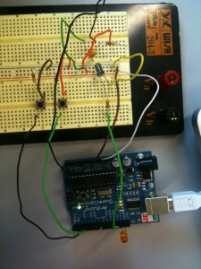
 Server:
- Vor dem Lichtsensor befindet sich ein 100K Widerstand
- Vor den Knöpfen befinden sich 10K Widerstände
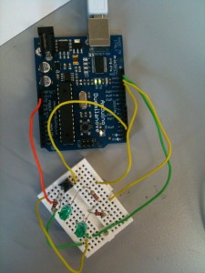
 Client:
 Sourcecode für Prozessing für SERVER
/* Processing Network Server controlling an Arduino

Arduino #1   is an IN and OUTPUT Device,
             connected to a Machine that runs a Processing Network Server
Arduino #2   is ALSO an IN and OUTPUT Device,
             connected to a Machine that runs a Processing Network Client

This is the SERVER. You have to find out your IP address and start it before the Client...
You can then send and receive data on both machines/ arduinos.
On both Arduinos we read DIN2, DIN3, and AIN0. This can be expanded of course.
We send the data in a byte array with a header of the number 255 -> [255, DIN2, DIN3, AIN0]
On the receiving end we map DIN2 to DOUT12, DIN3 to DOUT13 and AIN0 to DOUT9 (PWM).
*/

// Libraries -----------------------------
import processing.serial.*;
import cc.arduino.*;
import processing.net.*;

// Variables -----------------------------
Arduino arduino;
Server myServer;

color off = color(4, 79, 111);
color on = color(84, 145, 158);

// byte array to send
// [255, DIN2, DIN3, AIN0]
byte[] input = {byte(255), byte(0), byte(0), byte(0)};

// int array to receive data
int[] message = {0,0,0,0};
int dataInput = 0;

// Setup ---------------------------------
void setup() {
  size(470, 280);
  arduino = new Arduino(this, Arduino.list()[0], 57600);

  // Set pins 2 - 3 as Inputs
  for (int i = 2; i <= 3; i++)
    arduino.pinMode(i, Arduino.INPUT);

  // Set pins 13, 12, 9 as outputs
  for (int j = 12; j <= 13; j++)
    arduino.pinMode(j, Arduino.OUTPUT);

    arduino.pinMode(9, Arduino.OUTPUT);
    arduino.digitalWrite(13, Arduino.LOW);


  // start server
  myServer = new Server(this, 5204);

}

// Draw Loop ----------------------------------------------------
void draw() {
  background(off);
  stroke(on);

// read DIN2, DIN3 -----------------
  for (int x = 2; x <= 3; x++){
    if (arduino.digitalRead(x) == Arduino.HIGH){
      input[x-1] = 1;
      fill(on);
    }
    else {
      input[x-1] = 0;
      fill(off);
    }
   rect(420 - x * 30, 30, 20, 20);
  }


// check AIN0, scale to 0-255 and make it 254 if it is 255
// because 255 is used as header of our little protocol
  byte val = byte(arduino.analogRead(0) / 4);
  if (val == 255){
    val -= 1;
  }

  input[3] = val;

  // send data ----------------------------
  myServer.write(input);

  // read data ----------------------------
  Client thisClient = myServer.available();
  if (thisClient != null){
    dataInput = thisClient.read();
    if (dataInput == 255){
      message[0] = 255;
      message[1] = thisClient.read();
      message[2] = thisClient.read();
      message[3] = thisClient.read();
    }
  }
  println(message);

  // control arduino with the received data ---
  if (message[1] == 1){
    arduino.digitalWrite(12, Arduino.LOW);
  }
  if (message[1] == 0){
    arduino.digitalWrite(12, Arduino.HIGH);


  }

  // println(arduino.analogRead(2));
  if (arduino.analogRead(2) < 100){
    arduino.digitalWrite(13, Arduino.HIGH);
  }
  else {
    arduino.digitalWrite(13, Arduino.LOW);
  }

   arduino.analogWrite(9, message[3]);

  // draw analog inputs in window ---
  for (int i = 0; i <= 5; i++) {
    ellipse(280 + i * 30, 240, arduino.analogRead(i) / 16, arduino.analogRead(i) / 16);
  }
}
Sourcecode für Prozessing für CLIENT
/* Processing network Client controlling an Arduino

Arduino #1   is an IN and OUTPUT device
             connected to a Machine that runs a Processing Network Server
Arduino #2   is ALSO an IN and OUTPUT device
             connected to a machine that runs a Processing Network Client

This is the Client. Get the Server's IP address and start the server first.
You can then send and receive data on both machinges/ arduinos.
On both Arduinos we read DIN 2, DIN3 and AIN0. This can of course be expanded...
We send the data in a byte array with a header of the number 255 -> [255, DIN2, DIN3, AIN0]
On the receiving end we map DIN2 to DOUT 12, DIN3 to DOUT 13 and AIN0 to DOUT9 (PWM).

*/

// libraries ---------------------
import processing.serial.*;
import cc.arduino.*;
import processing.net.*;

// variables ---------------------
Arduino arduino;
Client myClient;

color off = color(4, 79, 111);
color on = color(84, 145, 158);

byte[] input = {byte(255), byte(0), byte(0), byte(0)};
byte val;

int[] message = {0, 0, 0, 0};

int dataInput;

// setup ---------------------------------------------------
void setup() {
  size(200, 200);

  println(Arduino.list());
  arduino = new Arduino(this, Arduino.list()[0], 57600);

  for (int i = 12; i <= 13; i++)
    arduino.pinMode(i, Arduino.OUTPUT);

  arduino.pinMode(9, Arduino.OUTPUT);

  for (int i = 2; i <= 3; i++)
    arduino.pinMode(i, Arduino.INPUT);

  myClient = new Client(this, "172.31.8.192", 5204);


}

// the draw loop -------------------------------------------
void draw() {
  background(off);
  stroke(on);

  // read data from server ------------------
  if (myClient.available() > 0){
    dataInput = myClient.read();

  // check for 255 and read thereafter
  // [255, DIN2, DIN3, AIN0]
    if (dataInput == 255){
      message[0] = dataInput;
      message[1] = myClient.read();
      message[2] = myClient.read();
      message[3] = myClient.read();
    }
    println(message);
  }

  // control arduino with the received data ----
  if (message[1] == 1){
    arduino.digitalWrite(12, Arduino.LOW);
  }
  if (message[1] == 0){
    arduino.digitalWrite(12, Arduino.HIGH);
  }

  if (message[2] == 1){
    arduino.digitalWrite(13, Arduino.LOW);
  }
  if (message[2] == 0){
    arduino.digitalWrite(13, Arduino.HIGH);
  }

  arduino.analogWrite(9, message[3]);

// read arduino pins and send to server ------------------------
  for (byte x = 2; x <= 3; x++){
    if (arduino.digitalRead(x) == Arduino.HIGH){
      input[x-1] = 1;
    } else {
      input[x-1] = 0;
    }
  }

 // 255 is used by our little protocol we have to shorten occuring 255 to 254
 val = byte(arduino.analogRead(0) /4);
 if (val == byte(255)){
   input[3] = byte(254);
 } else {
   input[3] = val;
 }

// send array to server -----------------------------------------
myClient.write(input);

}
Sourcecode für Anduino: StandardFirmata (Unter Exemples)