30. November 2010

http://students.washington.edu/acleone/codes/tlc5940arduino/html_r014/

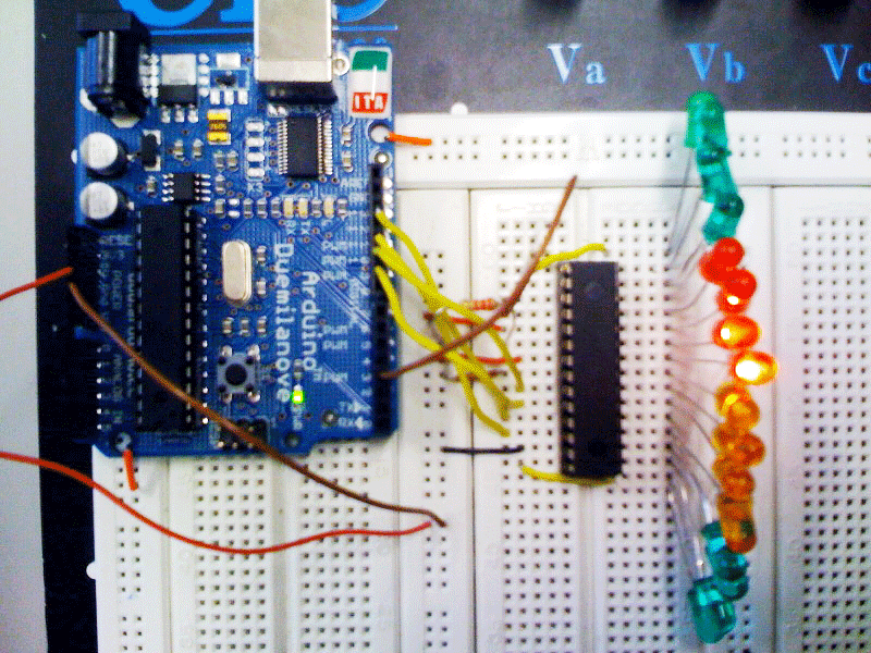
</p>
<p style="text-align: left;">/*
 Basic Pin setup:
 ------------                                  ---u----
 ARDUINO   13|-> SCLK (pin 25)           OUT1 |1     28| OUT channel 0
 12|                           OUT2 |2     27|-> GND (VPRG)
 11|-> SIN (pin 26)            OUT3 |3     26|-> SIN (pin 11)
 10|-> BLANK (pin 23)          OUT4 |4     25|-> SCLK (pin 13)
 9|-> XLAT (pin 24)             .  |5     24|-> XLAT (pin 9)
 8|                             .  |6     23|-> BLANK (pin 10)
 7|                             .  |7     22|-> GND
 6|                             .  |8     21|-> VCC (+5V)
 5|                             .  |9     20|-> 2K Resistor -> GND
 4|                             .  |10    19|-> +5V (DCPRG)
 3|-> GSCLK (pin 18)            .  |11    18|-> GSCLK (pin 3)
 2|                             .  |12    17|-> SOUT
 1|                             .  |13    16|-> XERR
 0|                           OUT14|14    15| OUT channel 15
 ------------                                  --------

 -  Put the longer leg (anode) of the LEDs in the +5V and the shorter leg
 (cathode) in OUT(0-15).
 -  +5V from Arduino -> TLC pin 21 and 19     (VCC and DCPRG)
 -  GND from Arduino -> TLC pin 22 and 27     (GND and VPRG)
 -  digital 3        -> TLC pin 18            (GSCLK)
 -  digital 9        -> TLC pin 24            (XLAT)
 -  digital 10       -> TLC pin 23            (BLANK)
 -  digital 11       -> TLC pin 26            (SIN)
 -  digital 13       -> TLC pin 25            (SCLK)
 -  The 2K resistor between TLC pin 20 and GND will let ~20mA through each
 LED.  To be precise, it's I = 39.06 / R (in ohms).  This doesn't depend
 on the LED driving voltage.
 - (Optional): put a pull-up resistor (~10k) between +5V and BLANK so that
 all the LEDs will turn off when the Arduino is reset.

 If you are daisy-chaining more than one TLC, connect the SOUT of the first
 TLC to the SIN of the next.  All the other pins should just be connected
 together:
 BLANK on Arduino -> BLANK of TLC1 -> BLANK of TLC2 -> ...
 XLAT on Arduino  -> XLAT of TLC1  -> XLAT of TLC2  -> ...
 The one exception is that each TLC needs it's own resistor between pin 20
 and GND.

 This library uses the PWM output ability of digital pins 3, 9, 10, and 11.
 Do not use analogWrite(...) on these pins.

 This sketch does the Knight Rider strobe across a line of LEDs.

 Alex Leone <acleone ~AT~ gmail.com>, 2009-02-03 */

#include "Tlc5940.h"

void setup()
{
 /* Call Tlc.init() to setup the tlc.
 You can optionally pass an initial PWM value (0 - 4095) for all channels.*/
 Tlc.init();
}

/* This loop will create a Knight Rider-like effect if you have LEDs plugged
 into all the TLC outputs.  NUM_TLCS is defined in "tlc_config.h" in the
 library folder.  After editing tlc_config.h for your setup, delete the
 Tlc5940.o file to save the changes. */

void loop()
{
 int direction = 1;
 for (int channel = 0; channel < NUM_TLCS * 16; channel += direction) {

 /* Tlc.clear() sets all the grayscale values to zero, but does not send
 them to the TLCs.  To actually send the data, call Tlc.update() */
 Tlc.clear();

 /* Tlc.set(channel (0-15), value (0-4095)) sets the grayscale value for
 one channel (15 is OUT15 on the first TLC, if multiple TLCs are daisy-
 chained, then channel = 16 would be OUT0 of the second TLC, etc.).

 value goes from off (0) to always on (4095).

 Like Tlc.clear(), this function only sets up the data, Tlc.update()
 will send the data. */
 if (channel == 0) {
 direction = 1;
 } else {
 Tlc.set(channel - 1, 1000);
 }
 Tlc.set(channel, 4095);
 if (channel != NUM_TLCS * 16 - 1) {
 Tlc.set(channel + 1, 1000);
 } else {
 direction = -1;
 }

 /* Tlc.update() sends the data to the TLCs.  This is when the LEDs will
 actually change. */
 Tlc.update();

 delay(50);
 }

}