Nora Gailer, Mona Neubauer, Thomas Schertenleib, Nicole Schulthess, David Simon, Florian Wachter, Jon Wirthner
Prototyping Processes
Starting Point
Our working group of 7 students started off with two different concepts and the idea of merging them during the development process:
Spacial network-construction
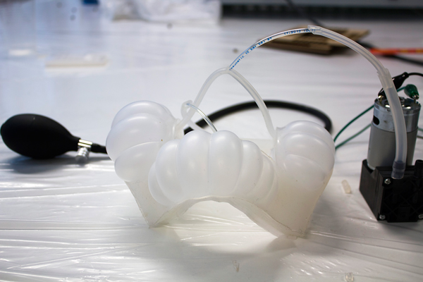
In the experiments we were very interested in pneu-nets which have a periphery movement instead of a central triggered one. For that we started with a rectangle frame in which we separated all four chambers, so we could inflate them individually. We were looking for a shape that is easy for building modular structures and polygon forms therefore we changed to a triangle shape. In further experiments we explored how we could get an inverse bending direction within the same pneu-net.
Pneu-Skeleton
In experiments of the first week, we came to the conclusion that pneu-nets could be combined with rigid elements to improve their ability to carry or move things. A rigid yet flexible skeleton would increase the pneu-nets potential through both, the amplification of the actuators movement as well as through the stabilisation of the silicone-shape. This allows for much bigger constructions consisting of multiple silicon-actuators.
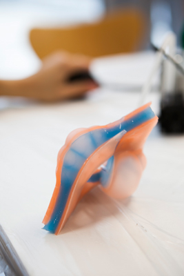
With this actuator we tried getting the shape to not only bend but curl up.
Because many of the so far tested actuators were very unstable and bad at passing on their motion to other elements, we have come up with a plan on how to attach them to a rigid yet flexible 'skeleton'.
Tensegrity
Idea / Thesis
Tensegrity-based structures have very interesting static behavior when built with flexible strings. Since all elements in these constructions are supporting each another, a single moving part can have great impact on the appearance of the whole network. We were interested in the ability to collapse and expand the whole "network" through the movement of one single element. Furthermore we saw flexible tensegrity-geometries as potential joints for a bigger moving construction because they can assume their original shape when their connecting strings get tied.
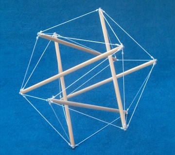
Tensegrity with 6 struts in the shape of an icosahedron. source
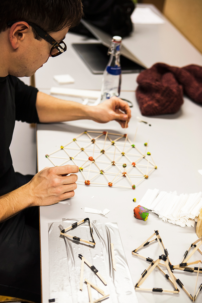
Step 1 - The 6-Strut icosahedron
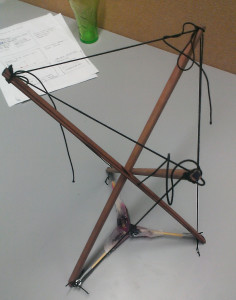
We first built a construction of six identical wooden sticks that where equally connected through an elastic band that ran though wholes at each end of the sticks. To improve the construction we later fixed the position of the rubber string to the rigid elements they where holding.
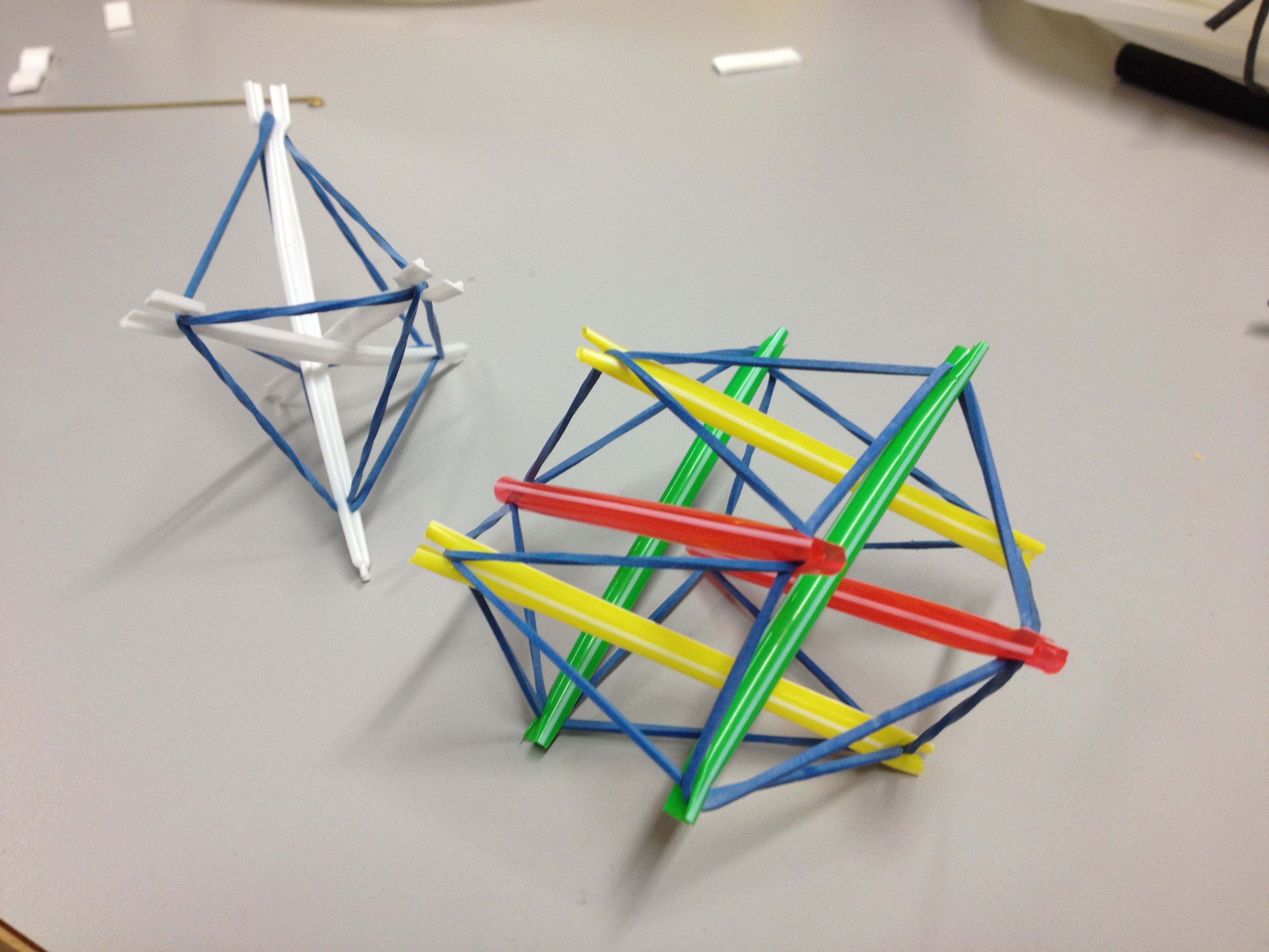
At this state all parallel sticks where tied together (two on each of the three axis). Through seperating the, the construction unfolded to the shape of an icosahedron.
reference to the mathematical backgrounds of the tensegrity of the icosahedron.
construction plan for an icosahedron tensegrity
Findings 1 - Collapse and rebuild
The prototype we built had great qualities at reconstructing its original shape but tended to "wear out" if the strings run loosely through the wholes of the sticks. By fixing the strings position to the wood we improved stability - at the cost of flexibility.
Step 2 - Adding actuators
We added triangular pneu-net actuators to the outside of the tensegrity structure in order to see what impact this could have on its geometry. After doing this with the "6-struted-tensegrities" we tried to transfer our experiments to a simplified tensegrity that had the same collapsing/expanding behavior but was based on only three rigid parts.
Findings 2 - Flexibility absorbs movement
The impact on both, the 6- as well as the 3-strut based tensegrities, was surprisingly little: The movements seemed to be absorbed by the flexible rubber bands around, thus having almost no impact on the rigid elements.
Step 3 - "passive reconstructors"
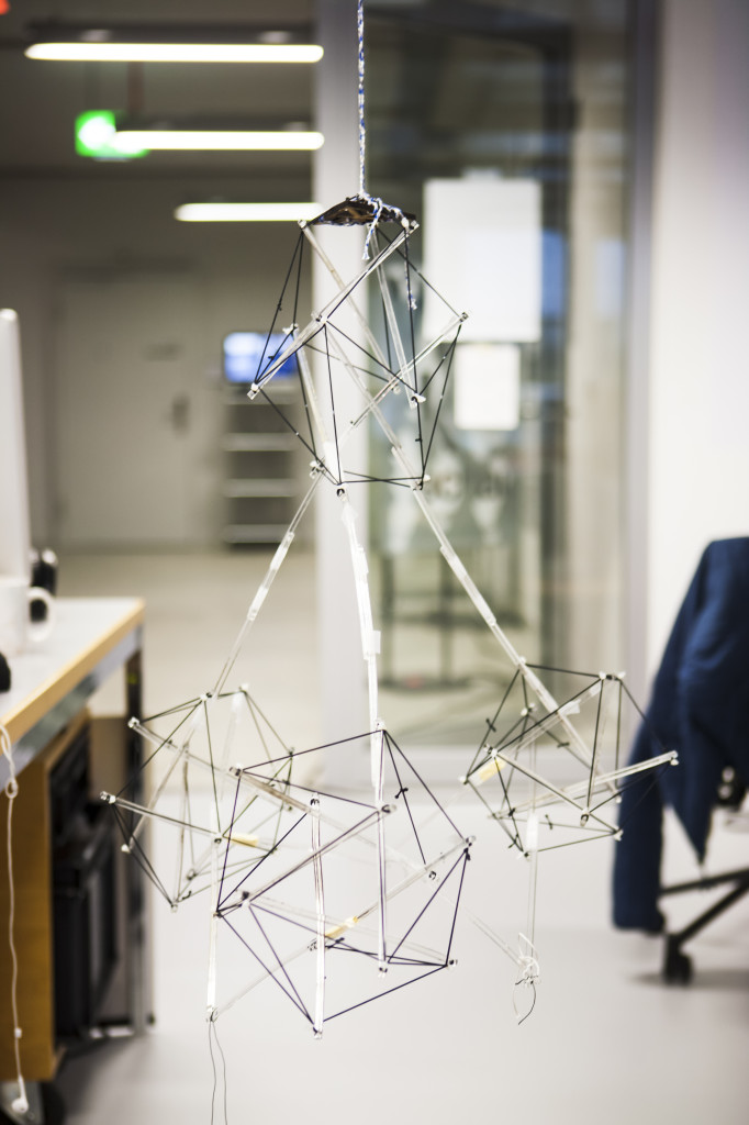
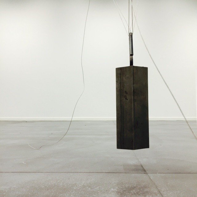
We decided to focus on the tensegritys quality of "rebuilding" the angles of its rigid parts and therefore not use them as actuator but as "passive reconstructors" on the opposite of the pneu-nets movement. To increase the actuators moving impact towards the tensegrity elements, we attached it at the interconnecting extensions of four symmetrically combined "6-strut icosahedrons".
Since this required a movement of only two one angle per actuator we build a new form of actuator. It was meant to pass a maximum of its movement on to the rigid structure holding it; originally it was created to actuate the "pneu-net skeletton" which was part of our initial idea described above.
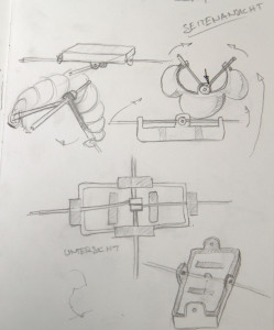
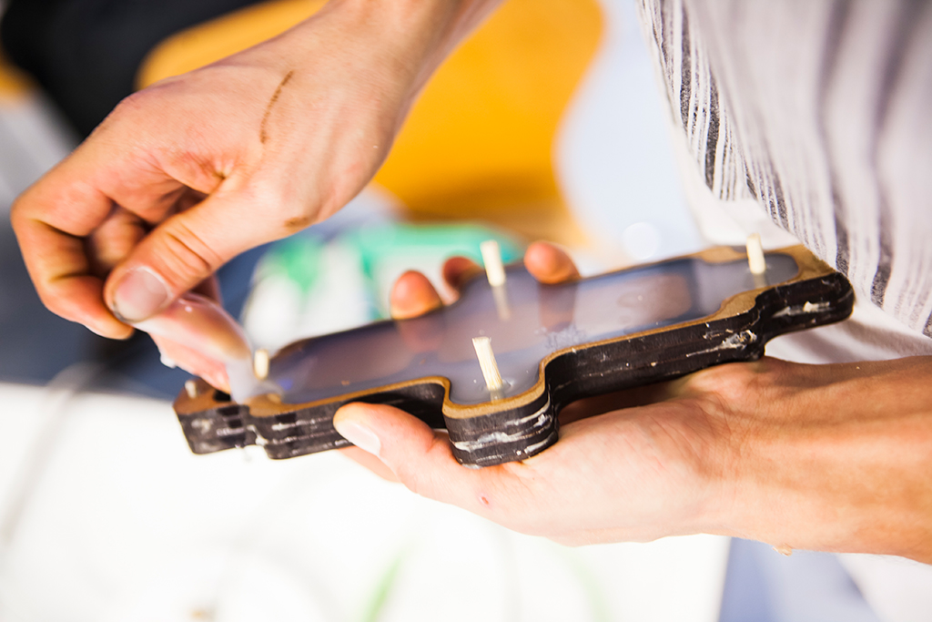
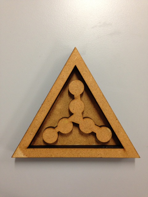
This is the blueprint for the mold we lasercut to build the new actuator.
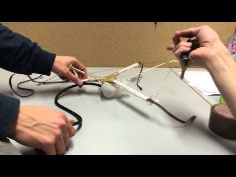
The actuator being tested on a separately on a "grid of crayons".
Findings 3 - Unexpected affordance
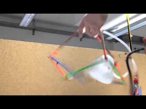
The actuator we built turned out to work well on its own, but could not convince with a great impact on the tensegrity-structure. It was too heavy for the icosahedrons-network, hence dragging it down too much. It also tended to loose its position since its rotation was only fixed on one axis. This led us to removing the pneu-neuts from the structure and explore another - unexpected - quality of the icosahedron-network: When hung up at its top triangular strings, a bouncing it will assemble all elements connected to the center. Bouncing the network rhythmically resulted in a seemingly "grabbing" agglomeration of elements. Furthermore the network provided the same quality of easing impacts and reassuming its original shape again.
The pyramid of icosahedral tensegrity with pneu-netic actuators on it.
The pyramid of icosahedral tensegrity being bounced and flattened.
Networks and Domes
Idea / Thesis
We where intending to come up with a bigger structure in which we could combine a greater number of identical pneu-net driven elements. We started this with a broad research towards symmetrical dome and network constructions. Since triangular shapes where chosen as the actuator we would use for our final piece, we focussed on constructions with triangular elements that could be moved with these.
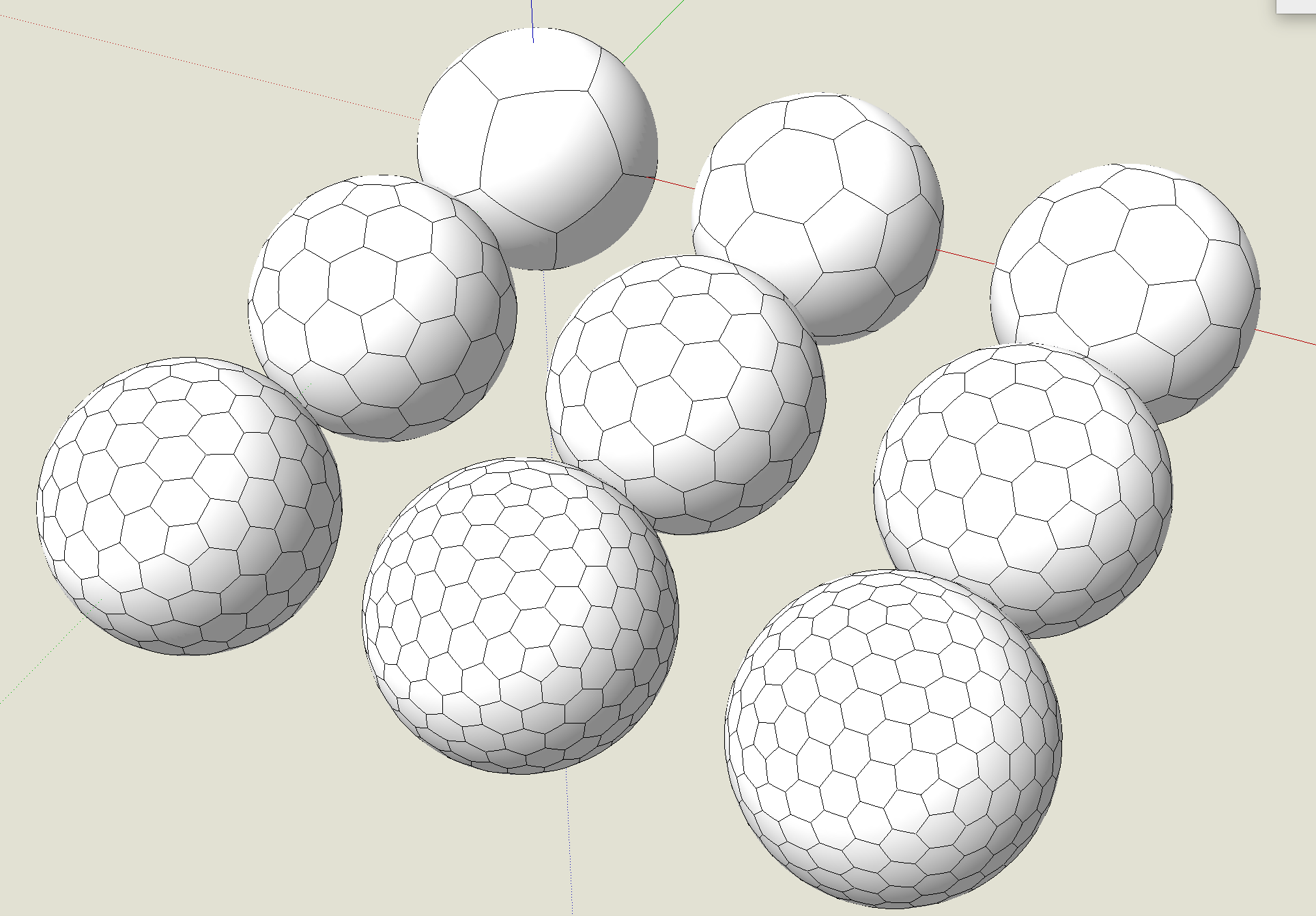
A sphere of triangles is a very stable construction, thus likely to restrain our actuators too much.
A sphere of triangles and pentagons would be more flexible.
Maybe we could also make use of our explorations toward tensegrity? Picture source
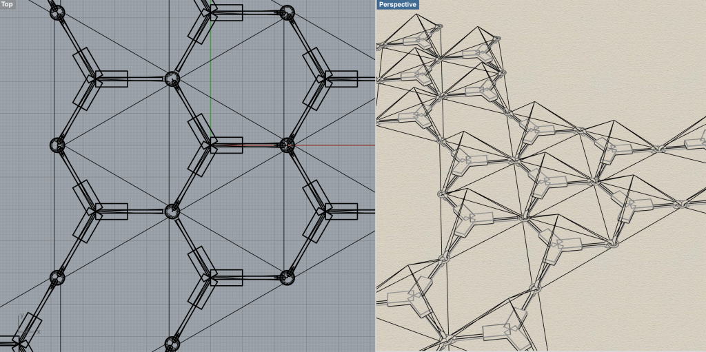
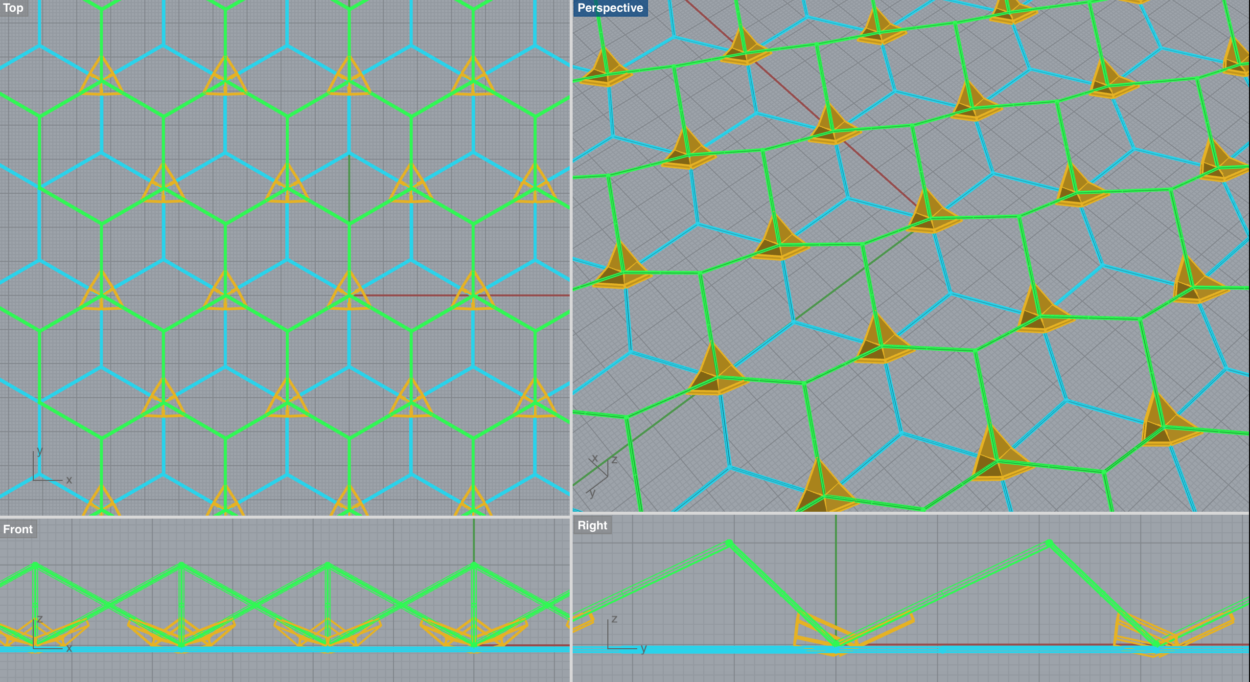
In this rendering we interconnected a flat hexagonal structure in a network of triangular actuators. To amplify their movement we added extending sticks to their corners, to stabilize and spread the movement we connected the sticks ends with a a web based on tensegrity.
Whilst hexagonal patterns spread horizontally, pentagonal networks fold up to a sphere when tied together.
Many of our models derived from templates on google's 3dWarehouse
Dome and Network Protoypes
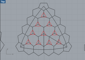
After reviewing and reconstructing many different geometries we merged a symmetry of 3, 4, and 5-cornered elements. It had a pentagon in its center bending the flat into a dome and hexagons around it to create straight side-walls. We got to this through analyzing the geometry of a "ball of squares" and digitally reconstructing it on a flat surface. That way we could find out where the 3, 4 and 5 cornered elements touched and which parts had to be loosen in order to contract/expand the whole. Thereby we found out that replacing the central pentagon with a hexagon would turn the convex dome structure into a flat surface that could be extended straightly. Based on this 3, 4, 5, and 6-sided structure we build a prototype from straws to see if our computer simulations where even possible in reality.
In this rendering we simulated a tensegrity structure in the center to add flexibility to the outspread sphere of pneu-netic triangels (black), elastic squares/pentagons (green) and stable pentagons(white).
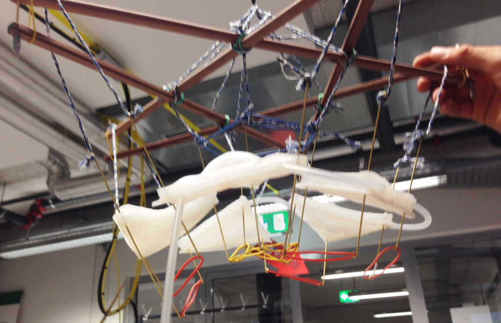
We built this dome from rigid elements only and planed to use it as a holding structure for an identical geometry beneath built from triangular actuators and elastic strings.
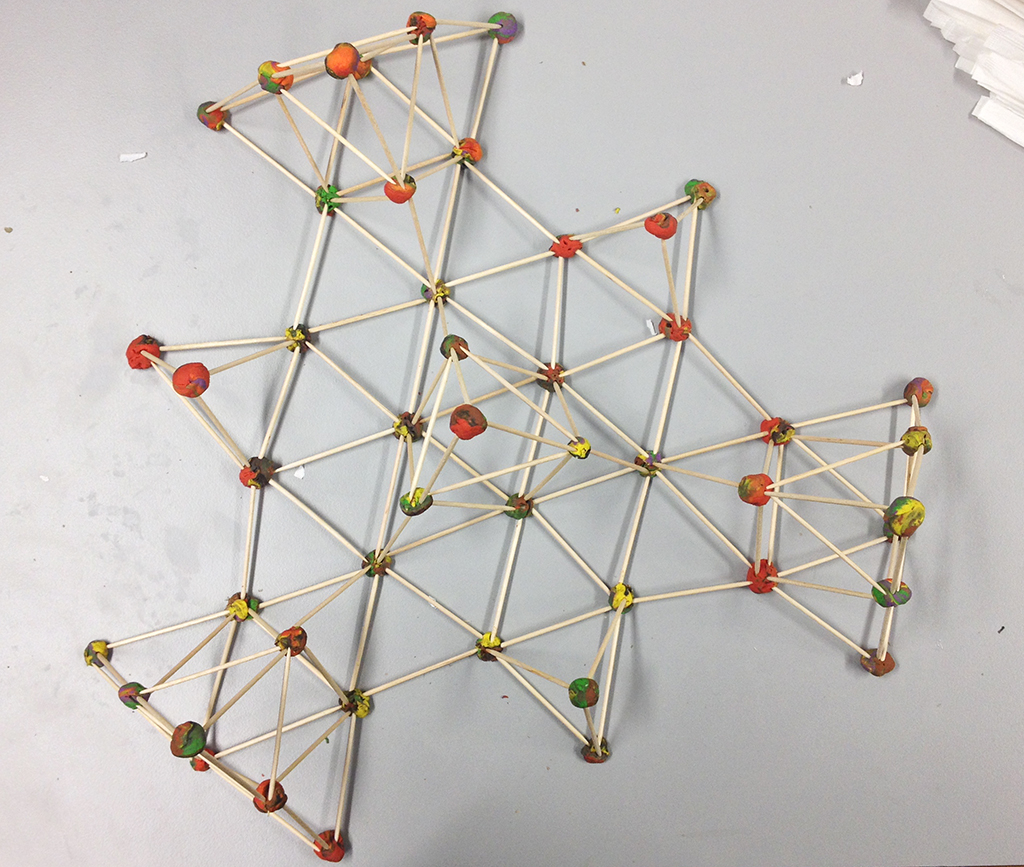
A rigid, self supporting structure we came up with by playing with left-over straws. It shall be named the "tripple-tensegible-scribble".
The geometry worked for most parts, except that we underestimated how strong the central pentagon would bent all walls toward the middle. Although the hexagon-geometry we attached to it was flat, the curve of the pentagon angled all wall toward the center and would have tied the whole into a closed sphere.
Prototype Dome II
To test the 'pneu-netic' movement of the triangles we used a more stable pentagonal rig to hang up a pentagonal order of triangular actuators. Unfortunately the video of this test is missing - however it could not prove much anyway because we had difficulties inflating all pillows of the five actuators simultaneously. Still it seemed the contraction of single actuators already tilted them towards the pentagonal whole in the middle of the structure.
Following this we tested interconnecting the extension-sticks of the triangles diagonally: When one triangle contracted, its bottom-strings pulled apart the top ends of its neighbor causing it to contract its bottom too. Although this was what we actually intended to happen we decided this would attach the triangles too rigidly to each another.
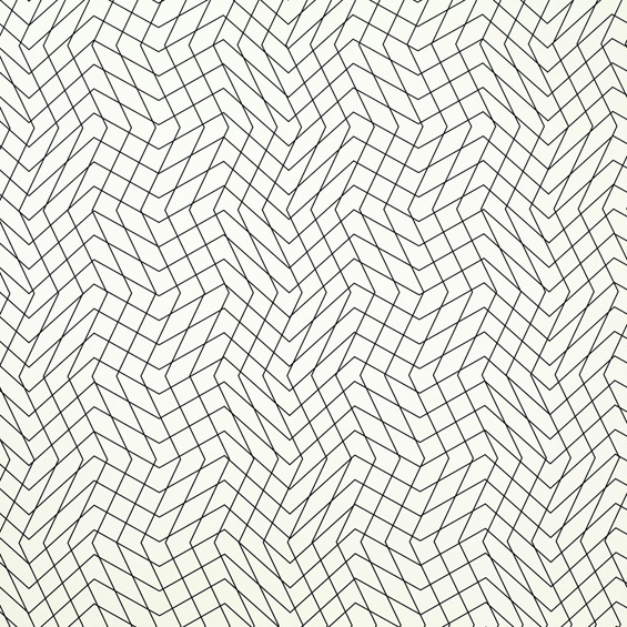
Further ideas towards triangular networks
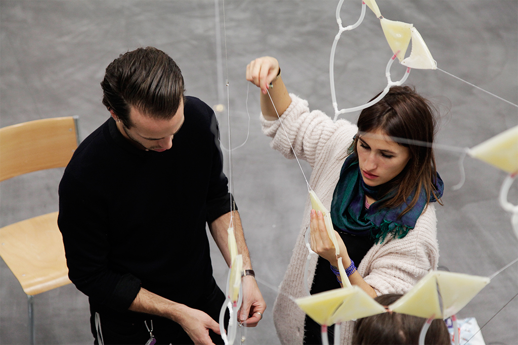
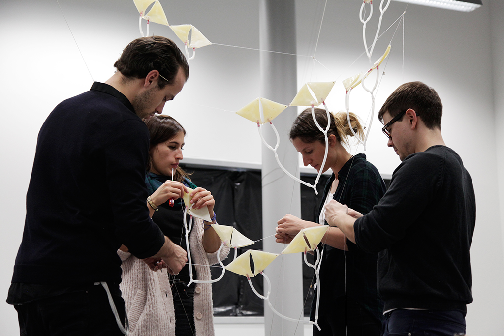
The project seemed to go more in the direction of a rather dense network of triangles only, so we started researching and modeling new structures. The tricky thing with triangles was that they constituted a very stable shape - so we considered hanging them up on threads would allow more space and flexibility to move among each another.
When things got too tricky to make up by mind we used simple materials to communicate our ideas and generate new ones.
Although the network seemed to have great potential in the rendering of the construction plan, building an testing it did not give us great results.
Triangular-Shadows
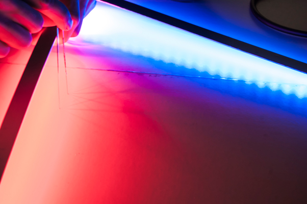
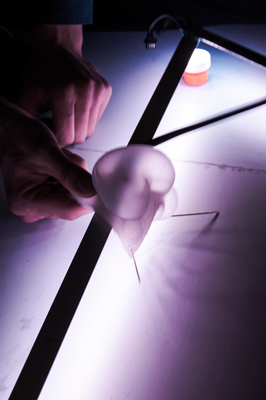
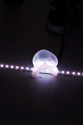
In parallel we had the idea to build a rigid structure with neon tubes/ LED stripes and attach the actuators to the structure. With the movement and bending of the pneu-nets we found fascintating shadow plays. The idea worked best along the stripes and when the light source is close to a surface (floor/ walls).
Protoype / Experiment
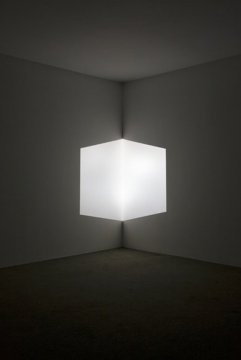
Subsequently, we had the idea to attach the LED stripes along the wall to give an optical illusion of an isometric cube/ triangle.
source
Cube-Illusion
Idea / Thesis
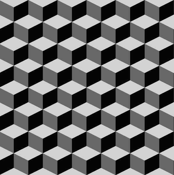
Our research on triangular structures led us to a flat of hexagonal tiles which - when combined with a triangular center axis - created the optical illusion of isometric cubes. We figured it would only take a little amount of movement and well angled light sources to give this effect a moving behavior that would even reinforce the perception of three-dimensional elements.
This pattern by Alessandro and Francesco Mendini was originally created for ceramic tiles but would also be interesting to be used as a grid for pneu-nets.
Cube Prototypes
We tried different arrangements of triangular pneu-nets inside rigid hexagonal structures that where interconnected by two separate triangles on the top and bottom center. We were trying to find a way using triangular pneu-nets move the two the cenrtal point apart from each other on the z-axis.
Having the actuator at the center bottom could not move the edges very far and made the construction tilt to one or another side.
Here we tried to achieve the separation of corners through activators on both sides of the cube. Again the construction tilted and - also due to the top activators weight - no cube could take shape.
How about doing it the opposite way around? When the actuator was „hanging through“ in its passive state, it was barely strong enough to fold up but could not tie the cube to a flat layer.
We decided to give this idea one more chance: We rebuild the construction with a stable wire, connected them with very loose ring-joints and attached all flexible parts to a rigid LED-panel. This time we pinched the extension of the actuators horizontally into the bottom silicon layer.
Turning this prototype upside down did not work too well either. But it sparked the idea of positioning the actuator not in the center but in-between the cubes folding up. This way it would not have to shift itself but would lift the corners in-between the cubes up to mid-height and therefore support the cube-shape in two ways. In the case of this standalone prototype it would require 3 actuator per cube to lift the center joint. However in a grid of a several cubes each actuator could also trigger three cubes!
Since we could not decide for neither of these prototypes, this idea could only be simulated in a digital model but will be further investigated.
String of Triangles
In a different approach we started with the idea to build a structure that has an initial point from where a movement can be started and then runs over the whole formation similar to a wave. Based on previous experiments we decided to go with a triangle formed pneu-net, which is very robust and let itself highly inflate. The spider net with its look and behaviour act as a referee. With threads and needles the pneu-net got sewed together and hanged up. We experienced that with this solution the structure has a movement but not a guided one. In a further step we first connected the pneu-net in elements of two very closely sewed together before use them in a bigger formation. Since we did know that we could achieve a bigger movement by having the more solid surface connected in invers direction we included this in our prototype. In the prototype each pneu-net bends invers direction makes the structure look like a snake. At the same time it extract together by inflating and stretched it by letting the air out again.
Findings
After having so many ideas and direction we voted in our group finally to go with the idea 'String of Triangle'. We started to build a hanging structure: an inverse pyramid shape.
Materials, Production Techniques, Modifications, Combinations, Technical Findings
Production Process
Triangle-Actuators
We decided to build the actuators connected together form a triangluar shape. As after different experiments, we found that this specific shape has a good bending property and is very stable. The stability gets even stronger with a round shape of the air chambers within the triangle. From the initial mould we made some changes in the thickness because the element immediately gets lighter if the there is less material used. The form of the air channel is slightly changed so that the oval form got smaller to the point of the edges.
Networking Actuators
To get an actual network of actuators, we hat to connect them somehow. Because of silicon having soft material property, we had to use loops through wich we put wire. We always connected two triangles on one side. One of those two with the fabric side on top and one with the fabric side on the bottom. These two triangles then together formed a rhomb. Then these two rhombs were connected on their angles once more in pairs of two. With this we get four actuators, wich we connected through two "Y" connecting elements. Because of the two sides being on the opposite, the two actuators form an "S" when pumped with air.
Hang on and hang them up!
Pump'em up!
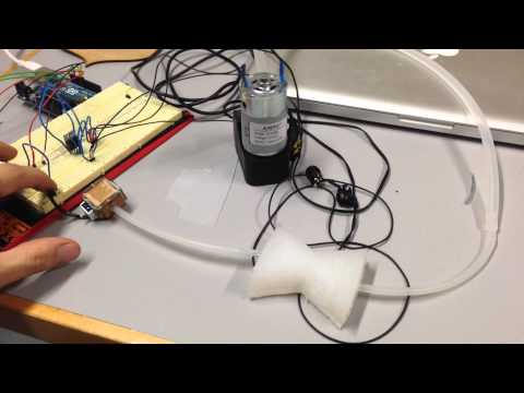
Our installation should be inflated and controlled from three sides. Therefore we had to develop a pump system, which is modularly connected, as we wanted to achieve a flexible positioning within the installation.
As we were restricted to 12 pumps, we decided to develop a prototype with three pumps. Firstly we've built the electronic control. As we didn't have any valves, and as theirs costs are enormously, we decided to build them ourselves. For that purpose we used a magnetic bolt module, which starts to initiate a pulling movement, when an electric current is applied. For the valve a specific cube-like chamber with two openings was developed and within the bolt was fixed. Tough the air could reach the chamber and via pulling mechanism it can be released.
For better functionality we stengthened the magnetic bot with a stronger spring and a silicone closure.
Thereafter we've built a box for the pumpes and valves, with three elements each. The box contains additionally a mount for the electronic equipement and for an arduino board. Three boxes were used in our installation.
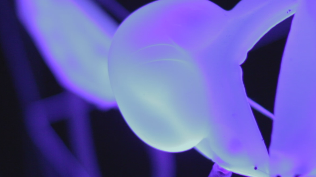
The final installation was a combination of the perception and intuitive decision made during building up the construction. Because we divided different task clearly we could work very efficiently and had a good work drive. One of the major questions was how to hang up the structure in the room and how to set the light. We worked directly in the room that we have chosen for the exhibition and could react on the space and size. The room was completely dark so that one could see the entities shining in the ultra-light. Not to know about the volume of the room supported the achieved atmosphere for the installation.
Videos/Pictures of the Installation + maybe Renderings/Sketches (only finalized, everything else in "Process")
 Because many of the so far tested actuators were very unstable and bad at passing on their motion to other elements, we have come up with a plan on how to attach them to a rigid yet flexible 'skeleton'.
 Tensegrity with 6 struts in the shape of an icosahedron. source
 Since this required a movement of only two one angle per actuator we build a new form of actuator. It was meant to pass a maximum of its movement on to the rigid structure holding it; originally it was created to actuate the "pneu-net skeletton" which was part of our initial idea described above.
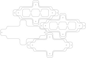 This is the blueprint for the mold we lasercut to build the new actuator.
 The actuator being tested on a separately on a "grid of crayons".
 The pyramid of icosahedral tensegrity with pneu-netic actuators on it.
The pyramid of icosahedral tensegrity being bounced and flattened.
The pyramid of icosahedral tensegrity with pneu-netic actuators on it.
The pyramid of icosahedral tensegrity being bounced and flattened.
 A sphere of triangles is a very stable construction, thus likely to restrain our actuators too much.
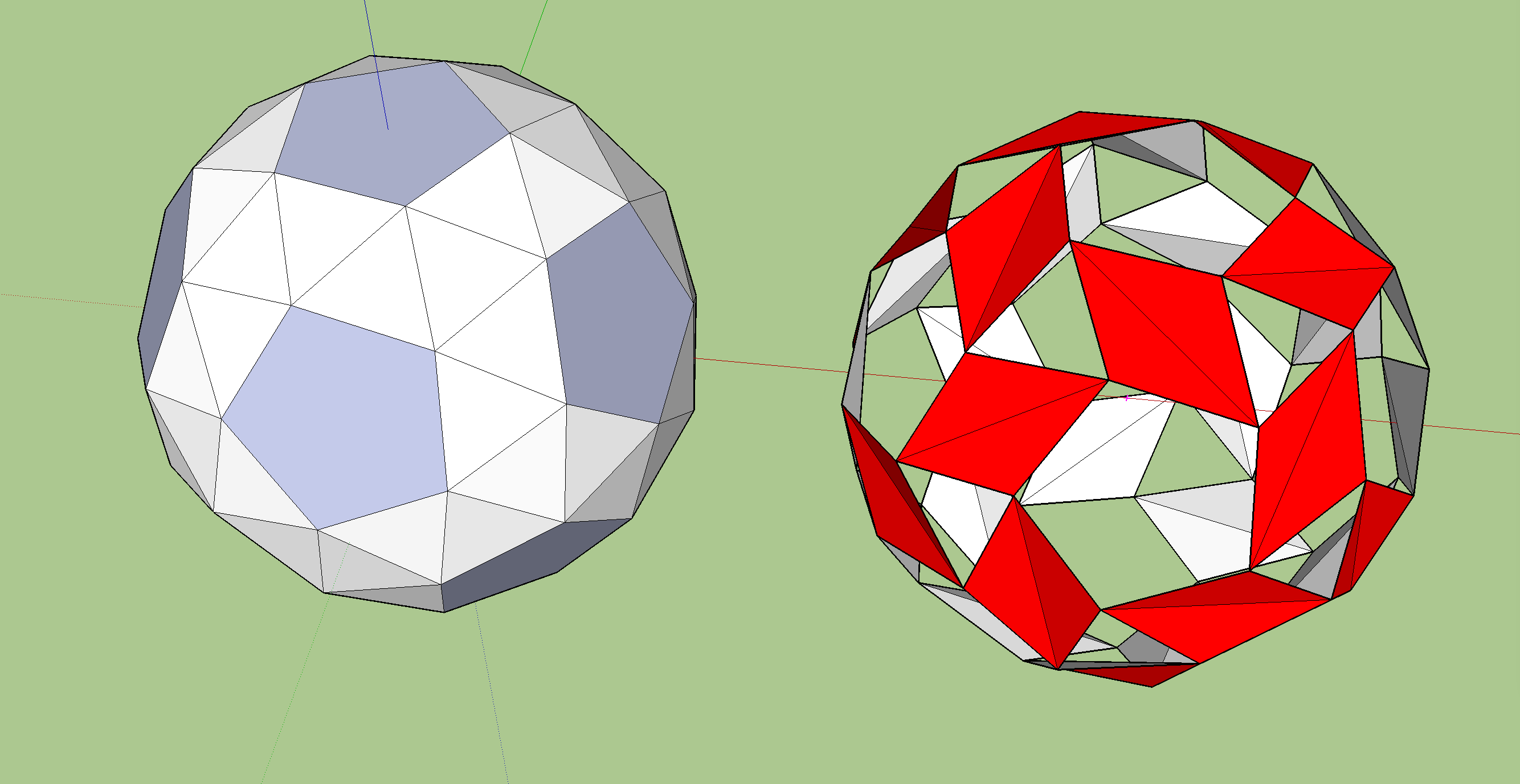 A sphere of triangles and pentagons would be more flexible.
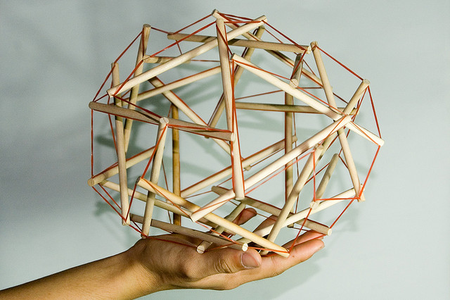 Maybe we could also make use of our explorations toward tensegrity? Picture source
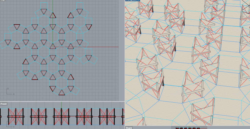 In this rendering we interconnected a flat hexagonal structure in a network of triangular actuators. To amplify their movement we added extending sticks to their corners, to stabilize and spread the movement we connected the sticks ends with a a web based on tensegrity.
 Whilst hexagonal patterns spread horizontally, pentagonal networks fold up to a sphere when tied together.
Many of our models derived from templates on google's 3dWarehouse
Whilst hexagonal patterns spread horizontally, pentagonal networks fold up to a sphere when tied together.
Many of our models derived from templates on google's 3dWarehouse
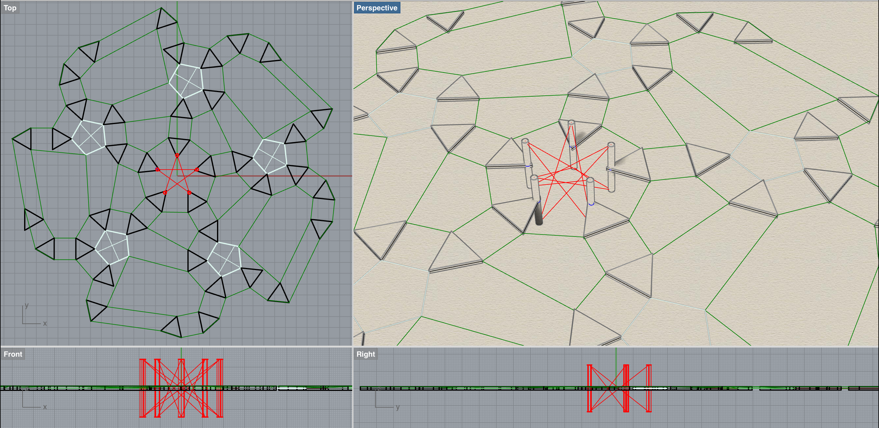 In this rendering we simulated a tensegrity structure in the center to add flexibility to the outspread sphere of pneu-netic triangels (black), elastic squares/pentagons (green) and stable pentagons(white).
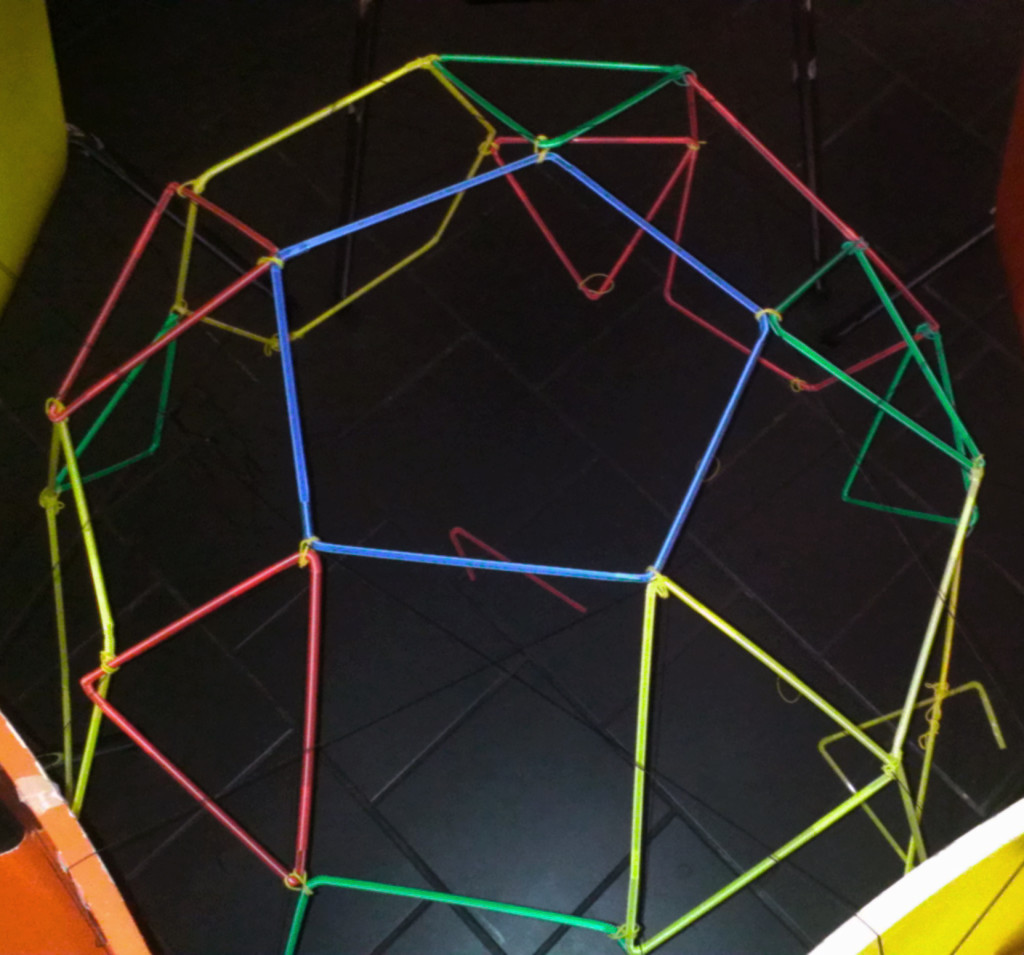 We built this dome from rigid elements only and planed to use it as a holding structure for an identical geometry beneath built from triangular actuators and elastic strings.
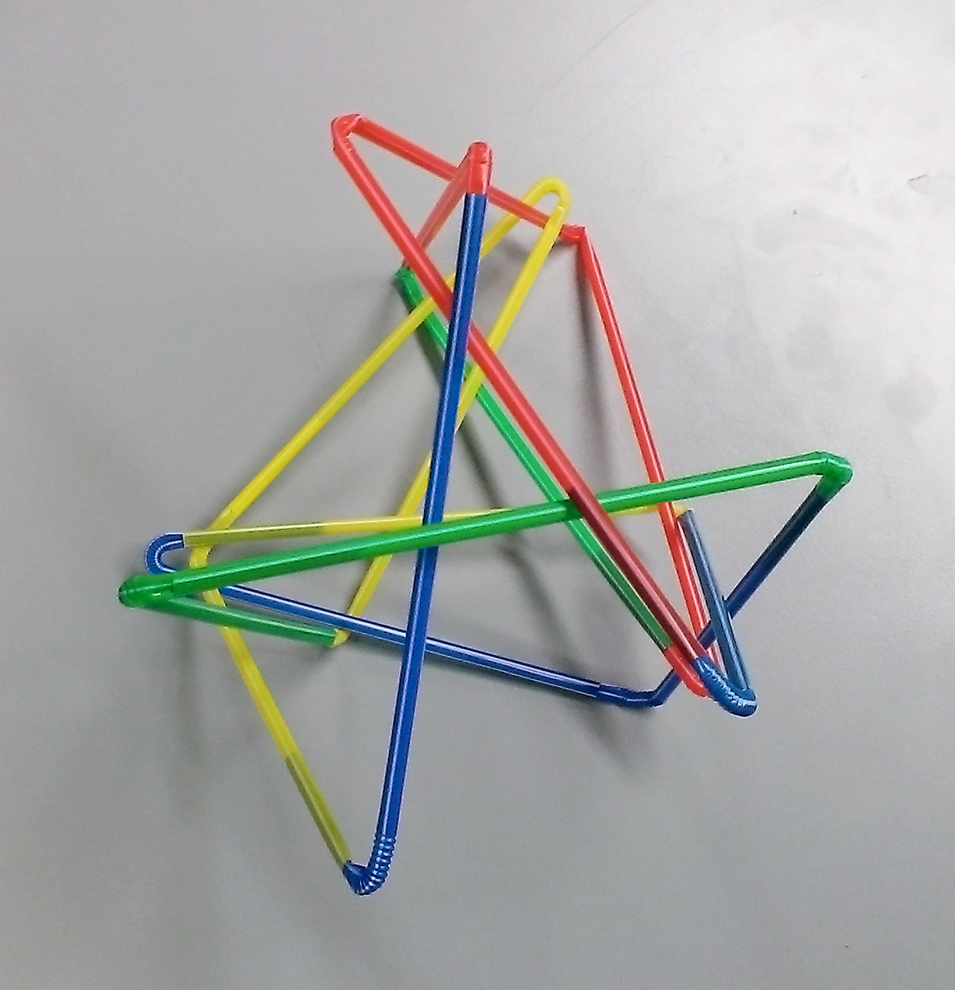 A rigid, self supporting structure we came up with by playing with left-over straws. It shall be named the "tripple-tensegible-scribble".
The geometry worked for most parts, except that we underestimated how strong the central pentagon would bent all walls toward the middle. Although the hexagon-geometry we attached to it was flat, the curve of the pentagon angled all wall toward the center and would have tied the whole into a closed sphere.
A rigid, self supporting structure we came up with by playing with left-over straws. It shall be named the "tripple-tensegible-scribble".
The geometry worked for most parts, except that we underestimated how strong the central pentagon would bent all walls toward the middle. Although the hexagon-geometry we attached to it was flat, the curve of the pentagon angled all wall toward the center and would have tied the whole into a closed sphere.
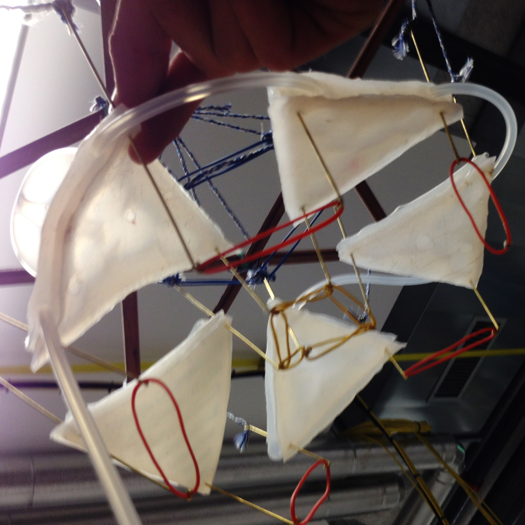 Following this we tested interconnecting the extension-sticks of the triangles diagonally: When one triangle contracted, its bottom-strings pulled apart the top ends of its neighbor causing it to contract its bottom too. Although this was what we actually intended to happen we decided this would attach the triangles too rigidly to each another.
 source
 This pattern by Alessandro and Francesco Mendini was originally created for ceramic tiles but would also be interesting to be used as a grid for pneu-nets.
 How about doing it the opposite way around? When the actuator was „hanging through“ in its passive state, it was barely strong enough to fold up but could not tie the cube to a flat layer.
We decided to give this idea one more chance: We rebuild the construction with a stable wire, connected them with very loose ring-joints and attached all flexible parts to a rigid LED-panel. This time we pinched the extension of the actuators horizontally into the bottom silicon layer.
How about doing it the opposite way around? When the actuator was „hanging through“ in its passive state, it was barely strong enough to fold up but could not tie the cube to a flat layer.
We decided to give this idea one more chance: We rebuild the construction with a stable wire, connected them with very loose ring-joints and attached all flexible parts to a rigid LED-panel. This time we pinched the extension of the actuators horizontally into the bottom silicon layer.
 Turning this prototype upside down did not work too well either. But it sparked the idea of positioning the actuator not in the center but in-between the cubes folding up. This way it would not have to shift itself but would lift the corners in-between the cubes up to mid-height and therefore support the cube-shape in two ways. In the case of this standalone prototype it would require 3 actuator per cube to lift the center joint. However in a grid of a several cubes each actuator could also trigger three cubes!

 Since we could not decide for neither of these prototypes, this idea could only be simulated in a digital model but will be further investigated.


 We decided to build the actuators connected together form a triangluar shape. As after different experiments, we found that this specific shape has a good bending property and is very stable. The stability gets even stronger with a round shape of the air chambers within the triangle. From the initial mould we made some changes in the thickness because the element immediately gets lighter if the there is less material used. The form of the air channel is slightly changed so that the oval form got smaller to the point of the edges.

 Thereafter we've built a box for the pumpes and valves, with three elements each. The box contains additionally a mount for the electronic equipement and for an arduino board. Three boxes were used in our installation.
 The final installation was a combination of the perception and intuitive decision made during building up the construction. Because we divided different task clearly we could work very efficiently and had a good work drive. One of the major questions was how to hang up the structure in the room and how to set the light. We worked directly in the room that we have chosen for the exhibition and could react on the space and size. The room was completely dark so that one could see the entities shining in the ultra-light. Not to know about the volume of the room supported the achieved atmosphere for the installation.
Videos/Pictures of the Installation + maybe Renderings/Sketches (only finalized, everything else in "Process")
The final installation was a combination of the perception and intuitive decision made during building up the construction. Because we divided different task clearly we could work very efficiently and had a good work drive. One of the major questions was how to hang up the structure in the room and how to set the light. We worked directly in the room that we have chosen for the exhibition and could react on the space and size. The room was completely dark so that one could see the entities shining in the ultra-light. Not to know about the volume of the room supported the achieved atmosphere for the installation.
Videos/Pictures of the Installation + maybe Renderings/Sketches (only finalized, everything else in "Process")